

Inside the Control Panels
The internal layout of each of the three Control Panels is similar. Around the inside edge of each Control Panel front are two strips of copper tape. Two sets run along either outside edge on the LEFT and RIGHT hand sides of the panel and a separate set of two strips runs around three sides of the panel facia itself. These are the ‘MAIN BUS’ – one for each Hand Controller - and the ‘ACCESSORY BUS’ – to power all of the point motors.
All Control Panels are wired in the same way. The ‘FEED’ and ‘RETURN’ wires from the DIN Sockets are each fed to one of the strips of copper tape along one side – one for the ‘FEED’ and the other for the ‘RETURN’.
Wires are then soldered to each of the copper strips and then to each of the ‘FEED SWITCHES’ on the panel.
Power to operate the locomotives on the upstairs layout is provided by ‘Gaugemaster’ Transformer Units. Each transformer has two separate outputs which can both power one hand held controller.
In all, three transformers have been used to power the entire layout and its locomotives. In Fig. 1 below we show the input and outputs from a transformer:
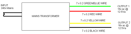
Fig.1 – A ‘Gaugemaster’ Mains Transformer
The connections between the Mains Transformer and the Hand Held Controllers are standard 4-Pin DIN type plug and socket.
The next two figures show these connectors for the MAIN STATION Control Panel. The LEFT HAND SIDE Hand Controller is shown in Fig.2
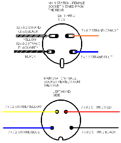
Fig 2 – Main Station Plug and Socket
The RIGHT HAND SIDE Hand Controller is shown in Fig.3
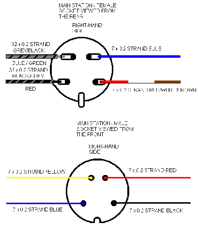
Fig 3 – Main Station Plug and Socket
The next two figures show these connectors for the LOW LEVEL Control Panel. The LEFT HAND SIDE Hand Controller is shown in Fig.4. This Controller controls the ‘UP’ Main Line going ‘CLOCKWISE’ around the layout
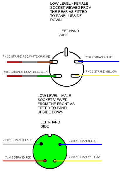
Fig 4 – Low Level Plug and Socket
The RIGHT HAND SIDE Hand Controller is shown in Fig.5. This Controller controls the ‘DOWN’ Main Line going ‘ANTI-CLOCKWISE’ around the layout.
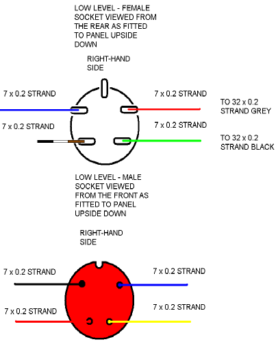
Fig 5 – Low Level Plug and Socket
The next two figures show these connectors for the HIGH LEVEL Control Panel. The LEFT HAND SIDE Hand Controller is shown in Fig.6. This Controller controls the ‘UP’ Main Line going ‘CLOCKWISE’ around the layout.
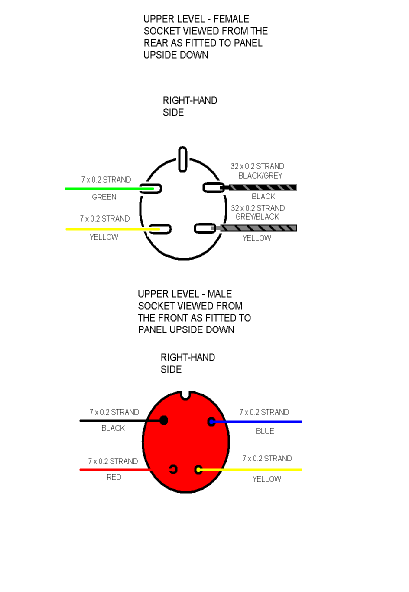
Fig 6 – High Level Plug and Socket
The RIGHT HAND SIDE Hand Controller is shown in Fig.7. This Controller controls the ‘DOWN’ Main Line going ‘ANTI-CLOCKWISE’ around the layout.
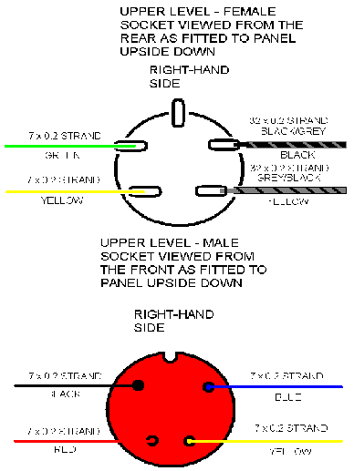
Fig 7 – High Level Plug and Socket